Articulations#
Articulations provide an alternative, and often superior approach to creating mechanisms versus adding joints to rigid bodies. Typically, you achieve higher simulation fidelity with articulations as they have zero joint error by design, and can handle larger mass ratios between the jointed bodies. PhysX simulates articulations in reduced-coordinates, where the configuration of the articulation is determined by its root body and the joint angles instead of the world pose of each body involved.
You can often turn jointed rigid bodies into an articulation - if they do not contain unsupported joints, see the Joint Table, and ensuring that loops are resolved appropriately. To enable articulation simulation on jointed rigid bodies, apply the articulation root component to the appropriate primitive.
Articulation Tree Structure#
Articulations must have a tree structure in terms of the rigid-body links and the joints between them (loops are possible, however). The tree structure is created solely by the Body 0 and Body 1 relationships of the joints connecting the articulation links (i.e. rigid bodies) - the USD hierarchy has no impact on the articulation structure other than during parsing, see below. Therefore, you may organize the joints and links in the stage tree as you see fit.
Here are two example articulations: A ragdoll and a robotic arm.

The tree structure for the arm is straightforward: The root is at the base on the ground plane, and revolute joints connect the different links up to the manipulator, where the tree has its only branch to connect the two gripper parts to the arm through prismatic (i.e. linear) joints.
For the ragdoll, we can choose any link, i.e. limb as the root and the resulting structure is always a tree. For example, we can choose the head to be the root, and connect the torso to it with a spherical joint, which in turn uses spherical joints to attach the arms, and so on.
Floating and Fixed-Base#
There is a key difference between the two articulation examples: The ragdoll is a floating articulation which means the root (e.g. the head) may move freely in space.
The robot arm is a fixed-base articulation: Its root or base is fixed to the world frame.
USD Hierarchy / Articulation Root#
You should consider the USD hierarchy when you apply the Articulation Root component to a prim such that one or more articulations are created.
The rules are as follows:
For a fixed-base articulation, add the Articulation Root component either to:
the fixed joint that connects the articulation base to the world, or
an ancestor of the fixed joint in the USD hierarchy. The second option allows creating multiple articulations from a single root component added to the scene: Each descendant fixed joint will be defining an articulation base link.
In the robotic-arm example above, we connect the robot’s base to the world frame using a fixed joint, and then could, for example, apply the root component to this joint.
For a floating-base articulation, add the Articulation Root component either to:
the root rigid-body link, or
an ancestor of the root link in the USD hierarchy.
In the ragdoll example, we could, for example, apply the root component to the head link.
Extensions and Articulations#
When you use extensions that access the underlying PhysX articulation data (e.g. omni.physx.tensors), it is beneficial to set up articulations such that their USD and PhysX topologies are identical - only then do you get a one-to-one relationship between USD and PhysX joint parameters such as limits and drive targets. The USD physics interface must provide identical behavior for articulation and regular joints, and it may therefore swap joint limits or negate joint drive targets when parsing from USD to the PhysX articulation; this is because USD joints do not have to follow the articulation topology, e.g., it may be that the body0 relationship does not point to the parent link in the PhysX articulation, but the USD joint limit is defined in the body0 to body1 joint frame order.
Closing Loops#
While articulations natively only support tree-structures, it is possible to create loops in the articulation by adding joints between articulation links that have the Exclude from Articulation flag enabled. For example, we could tie the ragdoll’s hands together by adding a distance joint between the two hand spheres.
UsdPhysicsJoint collisionEnabled#
It is currently not possible to respect this boolean for a joint that belongs to an articulation. Articulation itself does have a boolean defining whether articulation collides with self or not. We will try to fix this inconsistency in future releases.
JointStateAPI#
It is possible to add JointStateAPI to a joint prim. The state API holds the current state of the joint (position and velocity). This API can be used to store joint state in the middle of a simulation and save its current state. The simulation will then continue from this state.
Note
This is currently implemented only for joints that belong to an articulation.
Tendons#
Tendons create constraints within articulations. There are two types Fixed and Spatial
Fixed tendons impose constraints on joint positions. For example, fixed tendons are used to simulate the Shadow robotic hand in Isaac Gym: In a human finger, the motion of the two outermost joints is linked, which can be modeled with a fixed tendon.
Fixed Tendons#
The example video shows the Fixed Tendon snippet in Physics Demo Scenes > Snippets. The three articulation links are connected by two revolute joints. The red link is the articulation’s fixed base. The revolute joint connecting the red link to the first blue link features a joint drive that drives the joint alternatingly to zero and forty-five degrees. The second revolute joint connecting the two blue links does not have a drive, but is constrained to follow the position of the driven joint by a fixed tendon.
In particular, the fixed tendon in the snippet consists of two so-called tendon axes that each refer to one of the revolute joint positions. Each axis has a corresponding Gearing attribute that is used to compute an abstract tendon length from the gearing-weighted joint positions. The two gearing attributes are set to 1 and -1 respectively, such that the joint angles are equal if the tendon constrains its length to zero.
The fixed tendon enforces constraints on this length by applying spring-damper forces to the joints, like a joint drive, that are parametrized by the Stiffness and Damping attributes, and a per-axis Force Coefficient that scales the force applied at each axis, i.e. joint. In the demo, the tendon should only apply forces to the second, passive joint, so we set the force coefficient to zero for the drive-joint axis, and to -1 for the passive joint. It must be -1 in order for the tendon to drive the joint in the correct direction that reduces constraint violations.
In addition to the length constraints, you can add limit constraints by setting an upper and lower limit for the length, and an appropriate Limit Stiffness. This allows implementing one-sided constraints (with Stiffness set to zero).
Refer to the snippet Python code to learn more about the tendon dynamics, and sizing the stiffness and damping parameters based on gravity and articulation link mass.
Creating a Fixed Tendon#
When creating a fixed tendon, it is important to be aware of the articulation structure, since the tendon cannot link arbitrary joints in the articulation, but must follow the articulation structure exactly. In particular, all joint axes in the tendon must be connected to each other by exactly one articulation link.
This means that just like articulations, fixed tendons have a tree-like structure, and the root axis must be at the root of the tendon, i.e. applied to the articulation joint that is the single common ancestor of all other joints with axes in the tendon. For example in the snippet, the root axis must be on the joint between the red and blue link, as it is the articulation-ancestor of the second joint between the two blue links.
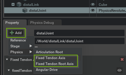
After identifying the root, apply the Fixed Tendon Root Axis (i.e. the PhysxTendonAxisRootAPI) using the Add button in the property window of the target joint. You are prompted for an instance name that is used to group axes into a single tendon.

Add additional Fixed Tendon Axis (i.e. PhysxTendonAxisAPI) to joints, taking the above structure constraints into account. Make sure to set the same instance name for all axes intended to be part of the same tendon. Then, proceed to configure gearings for all axes and common parameters in the root axis.
If the behavior is not as expected, make sure to check the log output for any warnings related to tendons.
Note
Fixed tendons currently only support Revolute and Prismatic joints. Support for Spherical and other joints will be added in the future.
Tendon axes are grouped into tendons by instance name, so make sure to use the same name for all axes belonging to the same tendon.
Spatial Tendons#
Spatial tendons impose distance constraints between attachment points on links. This allows, for example, modeling hydraulic actuators that can push and pull on links, artificial muscles in a biomimetic robot, or elastic-string-like mechanical components.
The example video above shows the Spatial Tendon Actuation snippet in Physics Demo Scenes > Snippets. The moving links of the two articulations are held up against gravity and actuated by tendons. The spheres are the debug visualization of the attachments that define the tendon geometry, and the blue lines visualize the line-of-sight distances that the tendons constrain using spring-damper forces.
The three different attachment-sphere colors distinguish the different types of attachments:
Root attachments (cyan) provide tendon-wide parameters such as spring-damper parameters, etc. The root attachments experience the reaction forces of the constraint forces applied to the leaf attachments.
Regular attachments (magenta) are used to route a tendon along articulation links. There is no force propagation through regular attachments, so they do not exert any forces on the links.
Leaf attachments (yellow) exert constraint forces to enforce a distance constraint on the path from the leaf to the root. A spatial tendon may branch, and, therefore, each leaf defines a sub-tendon with its own distance constraint. The leaf has sub-tendon specific parameters, such as the sub-tendon rest length and limits.
The tendon length of a (sub-)tendon is the sum of line-of-sight distances between the attachments on the path from a leaf to the root attachment. The tendon then applies spring-damper forces to the root and leaf to maintain a target length. In addition to a target length, you may set limits on the lengths, and choosing the upper and lower limit appropriately allows implementing one-sided constraints, e.g. modeling the tendon as an elastic string that can only constrain an upper length of the tendon.
The direction of the forces that are applied to roots and leaves is defined by the tendon geometry. For example, in the snippet above, the yellow leaf attachments apply a force to the moving links in the direction of the blue line towards the magenta middle attachment; analogously, the equal-magnitude root reaction force is also in the direction of the magenta middle attachment.
In the snippet, the two tendons demonstrate two separate approaches to actuation: The front tendon moves the middle attachment while keeping the target tendon length constant, while the other tendon changes the target tendon length. Further details such as sizing of the spring-damper parameters are presented in detail in the snippet Python code. Full details on the tendon dynamics are available in the USD schema documentation of PhysxTendonAttachmentRootAPI.
Creating a Spatial Tendon#

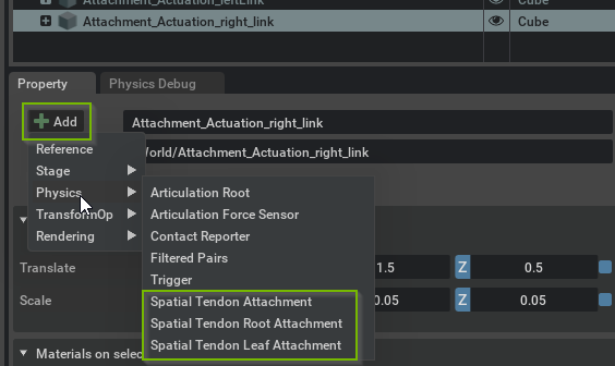
Spatial tendons are created by adding attachments to articulation links in the property window Add menu, see above. Since an articulation link may have multiple attachments, you must provide an instance name for each attachment.
The tendon (tree) structure is created by defining parent-child relationships between attachments. An attachment’s parent is defined by 1) the parentLink relationship that points to the articulation link that has the parent attachment, and 2) the parentAttachment token that specifies the instance name of the parent attachment. Note that unlike fixed tendons, spatial tendons are not constrained by the articulation structure.
The second Spatial Tendon snippet in Physics Demo Scenes > Snippets demonstrates a branching spatial tendon.
You may create a spatial tendon as follows:
Add a Spatial Tendon Root Attachment to an articulation link.
Add intermediate Spatial Tendon Attachment’s to links (note that it is possible to add multiple attachments belonging to the same tendon to the same articulation link).
Add a Spatial Tendon Leaf Attachment to terminate a sub-tendon, i.e. branch of the tendon tree.
Configure the connectivity of the tendon by defining the attachments’ parents (see the Authoring hints below for a graphical approach to this).
Configure gearings and the tendon-wide and sub-tendon parameters in the root and leaf, respectively.
Debug Visualization#
You can enable debug visualization for tendons in the Show/Hide (Eye) menu in the viewport, see screenshot. Choose Selected to visualize tendons related to a selected joint or link, or choose All to show all tendons in the stage, which is the recommended setting when editing Spatial Tendons in particular.
Further tendon-type-specific details on the visualization are provided in the respective sections.

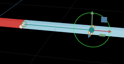
The debug visualization draws an overlay of lines and circles that represent the fixed tendon. The circles reflect the axes while the lines connect axes that belong to the same tendon. A solid circle highlights the tendon axis of the selected joint. Green indicates a regular axis, green-yellow a root axis, and red indicates an issue with an axis, most likely due to a structure issue, see the constraints above.
Finally, if there are multiple tendons running through a joint, you may highlight single tendons by clicking on the eye button in the tendon-axis display in the property window.
Force Sensors#
Note
Articulation force sensors are deprecated and will be removed in a future version.